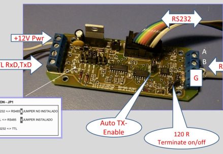
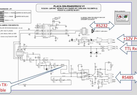
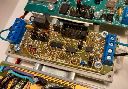
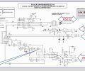
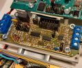
The DIN RS485 board / module from L&R Ing. contains a user-configurable circuit which allows it to be used in three different data communication systems. It can serve as a bridge a) between an RS-485 network and an RS232 port, b) between a conventional serial TTL (RxD/TxD 5V) port and RS485 (with Auto-Enable or external Enable TTL signal), or c) between the same 5V TTL port and an RS232 port, with only Rx and Tx signals. These configurations are set by jumpers JP1 on the board. A low-dropout LM2937-5 regulator supplies power for the circuit from an external source between 7 and 25 Vdc. Consumption is typically 0.05 A @ 12.8 V. A complete schematic diagram can be seen in Figure 2 and in:
DINRS485 board Schematics(PDF)
User Guide:
User Guide -DIN-RS485board- (PDF)
DINRS485 board Schematics(PDF)
User Guide:
User Guide -DIN-RS485board- (PDF)
